推力空氣軸承設計安裝指南
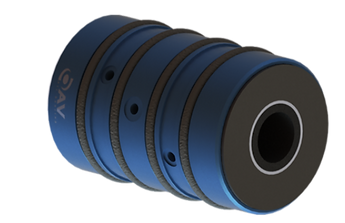
典型配置:推力空氣襯套像空氣襯套一樣在軸上滑動。唯一的區別是推力空氣襯套的兩側都有夾在軸上的面環,以防止推力空氣襯套線性移動。 OAV 安裝塊可用於固定推力空氣套管。如果使用客戶設計的外殼,請確保遵循與下面所示的空氣套管相同的準則。 空氣軸承製造商

如果軸與傳動帶一起旋轉,最好在每個軸上使用兩個推力軸承來抵消扭矩。傳動帶應始終放置在推力空氣襯套之間。如果這是不可能的,則將皮帶盡可能靠近第一個推力空氣襯套。靜態方程可用於確定每個止推襯套的負載要求。
下圖顯示了兩個常見示例,其中 F1 是驅動皮帶的張力,F2 和 F3 是作用在襯套上的力,d1 和 d2 是到皮帶和推力空氣襯套中心的距離:
.jpg)
設計和安裝指南
- 滾子空氣軸承
- 推力空氣軸承
- 空氣襯套
- 平面空氣軸承
圖 1. 兩個推力空氣襯套之間的傳動帶。這是推薦的,因為皮帶上的張力將分佈在兩個推力空氣襯套之間,如下面的等式所示。
F3 = F1* d1/(d1+d2)
F2 = F1* d2/(d1+d2)
假設:d1 = d2:
F2 = F3 = .5*F1

圖 2. 兩個推力空氣襯套外部的傳動帶。這種配置最適合小距離 d1 和長距離 d2。相應的載荷方程如下。
F2=F1*(d1/d2+1)
F3 = F1* d1/d2
考慮襯套和麵環之間的間隙可以忽略不計。端面軸環將靠在推力襯套的無摩擦表面上。一旦打開供氣,就會產生一個小間隙。因此,推力襯套系統的總長度可由下式確定:
左端面軸環長度 + 推力空氣套管長度 + 右端面軸環長度
Housing Installation
The three methods of housing installation are epoxy, O-rings, or a light-press fit. OAV mounting blocks allow for the epoxy
and O-ring methods of installation. In most cases it is recommended to design using O-rings, because O-rings have self-
aligning features that can be readjusted.
Designing With Epoxy:
If epoxy is used, make sure that the epoxy grooves on the bushings can be accessed with a syringe.
Designing With O-rings:
If O-rings are used, make sure to use the appropriate bore size and tolerance. OAV can also provide this information.
Designing With The Light-Press Fit Method:
If a light-press fit method is used, make sure to use the recommended bore size and tolerances. OAV can also provide this
information.
Other Considerations:
Air bushings rely on the straightness of the shaft. Design so that the deflection/displacement of the shaft is minimal.
Installing bushings with O-rings:
1) First do a quick visual inspection to ensure that there are no sharp edges in the bore of the mounting block. The o-rings
provide a very tight fit and if they get damaged, they will not work properly.
2) Lubricate the O-rings and surfaces with alcohol.
3) Press-fit the bushing inside the mounting block.
4) Insert the shaft and apply the air pressure. 30 PSI is enough to test the bushing without any load being applied.
5) Use proper alignment. If two shafts are used side-by-side, it is best to use gages to assure that the shafts are at an equal
distance from both ends. Parallelism is crucial for optimal performance of the air bushings.
Installing Bushings With Epoxy:
1) Clean the surfaces with alcohol.
2) Slide the air bushing into the mounting block, and the shaft into the bushing.
3) Align the shaft(s) with the best parallelism possible. If two shafts are used side-by-side, it is best to use gages to ensure
that the shafts are at equal distance at both ends. Parallelism is crucial for the performance of the air bushings.
4) Turn the air supply on at 30 PSI and do not apply any load to the bushing.
5) Use a syringe to apply the epoxy through the syringe holes on the mounting block until the epoxy fills the epoxy grooves
on the bushing. Make sure that the air port on the bushing lines up with the air port on the mounting block.
6) Keep the air supply on at 30 PSI until the epoxy cures.
7) Epoxy installation should only be performed after shaft alignment is confirmed
Installing Bushings With The Light-Press Fit Method:
1) Clean the surfaces with alcohol.
2) Light-press fit the air bushing into the mounting block, and the shaft into the bushing.
3) Align the shaft(s) with the best parallelism possible. If two shafts are used side-by-side, it is best to use gages to ensure
that the shafts are at equal distance at both ends. Parallelism is crucial for the performance of the air bushings.
4) Make sure that the air port on the bushing lines up with the clearance hole on the mounting block.
5) Install the air fitting directly into the air bushings as shown above.
Shaft and Face Collar Installation
1) Clean shaft surface with alcohol and a lint free cloth. Check for any surface imperfections. Shaft surface finish should
be 16 RMS or better.
2) Insert shaft in bushing with operating air on.
3) Clean face collar working surfaces with alcohol and a lint free cloth. Check for any surface imperfections.
4) Install first face collar in position on the shaft and tighten firmly.
5) Install second face collar on the shaft, press against the graphite thrust face with the operating air on, and tighten firmly. Gap will be set automatically by running air.
Mounting Alignment:
Mounting blocks should be installed in their permanent position after shaft install or secured loosely during shaft
installation. This will allow alignment adjustment between the block, O-ring compression, and running air. Mounting
blocks should be secured firmly after shaft installation and alignment is confirmed.
Temperature Controlled Thrust Air Bearings:
The temperature control bearings have three ports – the center port for bearing operating air, and ports on either side the
inlet and “exhaust” of temperature control fluid. Operating air and temperature control fluid do not interact withing the
bearing. Any fluid can be used, but air is most common. Operating air inlet and circulating fluid inlet should be
independent feeds to control pressure, flow, and temperature as needed.
Extreme Temperature Conditions
At temperatures below freezing, water will be drawn out of the air and can crystallize internally, impeding flow and
degrading performance of the bearing. This crystallization can occur in both operating air and temp control fluid when air is
used. Severity and likelihood of occurrence are dependent on severity of temperature, operating pressures, flows, ambient
humidity. This can be counter acted by using:
1) An in-line air heater
2) Compressed air dehumidifier
3) Pure compressed gas, such as helium or nitrogen (where practical), due to the homogenous state lacking water
contamination.
At high temperatures, maximum exposure temperature is dependent on application and precision needs, and control may be
aided with refrigeration of air and circulating fluid.