Guida alla progettazione e all'installazione del cuscinetto pneumatico di spinta
Configurazione tipica: le boccole dell'aria di spinta scorrono sull'albero proprio come le boccole dell'aria. L'unica differenza è che le boccole dell'aria reggispinta hanno collari frontali fissati all'albero su entrambi i lati per evitare che le boccole dell'aria reggispinta si muovano linearmente. I blocchi di montaggio OAV possono essere utilizzati per sostenere le boccole dell'aria di spinta. Se viene utilizzato un alloggiamento progettato dal cliente, assicurarsi di seguire le stesse linee guida mostrate di seguito per le boccole dell'aria. Produttore di cuscinetti ad aria

Se l'albero viene ruotato con una cinghia di trasmissione, è meglio utilizzare due cuscinetti assiali per albero per contrastare la coppia. La cinghia di trasmissione deve essere sempre posizionata tra le boccole dell'aria di spinta. Se ciò non è possibile, tenere la cinghia il più vicino possibile alla prima boccola dell'aria di spinta. Le equazioni statiche possono essere utilizzate per determinare il carico richiesto su ciascuna boccola reggispinta.
I diagrammi seguenti mostrano due esempi comuni in cui F1 è la tensione della cinghia di trasmissione, F2 e F3 sono le forze che agiscono sulle boccole e d1 e d2 sono le distanze dal centro della cinghia e delle boccole dell'aria di spinta:
.jpg)
Guide alla progettazione e all'installazione
- Cuscinetto pneumatico a rulli
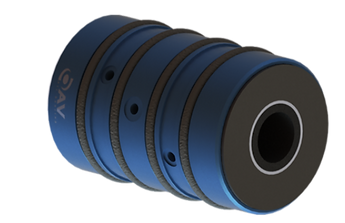
- Cuscinetto ad aria di spinta
- Boccola dell'aria
- Cuscinetti pneumatici piatti
Figura 1. La cinghia di trasmissione tra le due boccole dell'aria di spinta. Questo è consigliato, poiché la tensione sulla cinghia sarà distribuita tra entrambe le boccole dell'aria di spinta come mostrato nelle equazioni seguenti.
F3 = F1* d1/(d1+d2)
F2 = F1* d2/(d1+d2)
Supponendo: d1 = d2:
F2 = F3 = 0,5*F1

Figura 2. La cinghia di trasmissione all'esterno delle due boccole dell'aria di spinta. Questa configurazione funziona meglio con una piccola distanza d1 e una lunga distanza d2. Di seguito sono riportate le equazioni di carico corrispondenti.
F2=F1*(d1/d2+ 1)
F3 = F1* d1/d2
Considerare trascurabile lo spazio tra la boccola e il colletto frontale. Il collare frontale sarà posizionato contro la superficie priva di attrito della boccola reggispinta. Una volta attivata l'alimentazione dell'aria, verrà creato un piccolo spazio vuoto. Pertanto, la lunghezza totale del sistema di boccole reggispinta può essere determinata dalla seguente formula:
lunghezza del collare frontale sinistro + lunghezza della boccola dell'aria di spinta + lunghezza del colletto frontale destro
Housing Installation
The three methods of housing installation are epoxy, O-rings, or a light-press fit. OAV mounting blocks allow for the epoxy
and O-ring methods of installation. In most cases it is recommended to design using O-rings, because O-rings have self-
aligning features that can be readjusted.
Designing With Epoxy:
If epoxy is used, make sure that the epoxy grooves on the bushings can be accessed with a syringe.
Designing With O-rings:
If O-rings are used, make sure to use the appropriate bore size and tolerance. OAV can also provide this information.
Designing With The Light-Press Fit Method:
If a light-press fit method is used, make sure to use the recommended bore size and tolerances. OAV can also provide this
information.
Other Considerations:
Air bushings rely on the straightness of the shaft. Design so that the deflection/displacement of the shaft is minimal.
Installing bushings with O-rings:
1) First do a quick visual inspection to ensure that there are no sharp edges in the bore of the mounting block. The o-rings
provide a very tight fit and if they get damaged, they will not work properly.
2) Lubricate the O-rings and surfaces with alcohol.
3) Press-fit the bushing inside the mounting block.
4) Insert the shaft and apply the air pressure. 30 PSI is enough to test the bushing without any load being applied.
5) Use proper alignment. If two shafts are used side-by-side, it is best to use gages to assure that the shafts are at an equal
distance from both ends. Parallelism is crucial for optimal performance of the air bushings.
Installing Bushings With Epoxy:
1) Clean the surfaces with alcohol.
2) Slide the air bushing into the mounting block, and the shaft into the bushing.
3) Align the shaft(s) with the best parallelism possible. If two shafts are used side-by-side, it is best to use gages to ensure
that the shafts are at equal distance at both ends. Parallelism is crucial for the performance of the air bushings.
4) Turn the air supply on at 30 PSI and do not apply any load to the bushing.
5) Use a syringe to apply the epoxy through the syringe holes on the mounting block until the epoxy fills the epoxy grooves
on the bushing. Make sure that the air port on the bushing lines up with the air port on the mounting block.
6) Keep the air supply on at 30 PSI until the epoxy cures.
7) Epoxy installation should only be performed after shaft alignment is confirmed
Installing Bushings With The Light-Press Fit Method:
1) Clean the surfaces with alcohol.
2) Light-press fit the air bushing into the mounting block, and the shaft into the bushing.
3) Align the shaft(s) with the best parallelism possible. If two shafts are used side-by-side, it is best to use gages to ensure
that the shafts are at equal distance at both ends. Parallelism is crucial for the performance of the air bushings.
4) Make sure that the air port on the bushing lines up with the clearance hole on the mounting block.
5) Install the air fitting directly into the air bushings as shown above.
Shaft and Face Collar Installation
1) Clean shaft surface with alcohol and a lint free cloth. Check for any surface imperfections. Shaft surface finish should
be 16 RMS or better.
2) Insert shaft in bushing with operating air on.
3) Clean face collar working surfaces with alcohol and a lint free cloth. Check for any surface imperfections.
4) Install first face collar in position on the shaft and tighten firmly.
5) Install second face collar on the shaft, press against the graphite thrust face with the operating air on, and tighten firmly. Gap will be set automatically by running air.
Mounting Alignment:
Mounting blocks should be installed in their permanent position after shaft install or secured loosely during shaft
installation. This will allow alignment adjustment between the block, O-ring compression, and running air. Mounting
blocks should be secured firmly after shaft installation and alignment is confirmed.
Temperature Controlled Thrust Air Bearings:
The temperature control bearings have three ports – the center port for bearing operating air, and ports on either side the
inlet and “exhaust” of temperature control fluid. Operating air and temperature control fluid do not interact withing the
bearing. Any fluid can be used, but air is most common. Operating air inlet and circulating fluid inlet should be
independent feeds to control pressure, flow, and temperature as needed.
Extreme Temperature Conditions
At temperatures below freezing, water will be drawn out of the air and can crystallize internally, impeding flow and
degrading performance of the bearing. This crystallization can occur in both operating air and temp control fluid when air is
used. Severity and likelihood of occurrence are dependent on severity of temperature, operating pressures, flows, ambient
humidity. This can be counter acted by using:
1) An in-line air heater
2) Compressed air dehumidifier
3) Pure compressed gas, such as helium or nitrogen (where practical), due to the homogenous state lacking water
contamination.
At high temperatures, maximum exposure temperature is dependent on application and precision needs, and control may be
aided with refrigeration of air and circulating fluid.