DESIGN GUIDE
FOIL AIR BEARINGS Design and Installation Guide
This guide provides engineering best practices for the design, preload configuration, and installation of OAV Foil Air Bearings. Follow these recommendations to achieve optimal performance, stiffness, and accuracy.
01
Bearing Types
Foil Thrust Bearing
Supports axial (thrust) loads. Allows free radial motion.

Typical Use:
-
Axial load support
Foil Journal Bearing
Supports radial loads. Allows free axial motion.

Typical Use:
-
Radial load support
-
Shaft Guidance
02
Design Principles
SELF ACTING
Foil bearings create their own gas film during operation. No external pressurization is required.
CLEARANCE CRITICAL
Proper clearance (7 - 12.5 μm) ensure stable lift-off and low friction.
THERMAL STABILITY
Maintain dimensional stability of the housing and shaft over the operating temperature range.
CLEAN AIR
Use clean, dry air if purge is required. Filtration to less than 1 micron is recommended.
Design & Installation Guides
Modular Air Bearings
Tapered Air Bearings
Linear Guide Air Bearings
03
Axial & Radial Clearances
The shaft must pass freely through the bearing’s inner diameter (ID) without friction or binding. Set the axial clearance (the gap between the top foil and the runner surface) to 7.5 – 12.5 μm (0.00030 – 0.00050 in).
Foil Thrust Bearing
Axial clearance between top foil and runner surface.
Target: 7.5 - 12.5 μm

Shaft / Rotor
7.5 - 12.5 μm
Foil Journal Bearing
Radial clearance between top foil and rotor.
Target: 7.5 - 12.5 μm

7.5 - 12.5 μm
Shaft / Rotor
Measurement
Use calibrated shims or feeler gauges at 0°, 90°, 180°, and 270° to ensure uniform clearance around the rotating assembly. After shimming, verify free rotation by hand before performing break-in at low speed. Adjust housing, rotor, or runner position to achieve uniform clearance.
04
Housing & Mounting Requirements
The mounting structure locates and retains the foil bearing within the housing while maintaining alignment and concentricity. Hole patterns, dowel locations, and retention features should match the system datum scheme and application requirements.
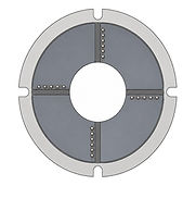
Foil Thrust Bearing
Use precision dowel alignment and controlled retention to locate the thrust bearing within the mounting structure. Maintain concentricity and base plate flatness relative to the shaft axis. Clean all mating surfaces with lint-free wipes and isopropyl alcohol only.

Base Plate
Dowel Pins
Foil Journal Bearing
Mount the journal bearing within a precision housing bore using controlled transition fits (e.g., ISO H7/g6) or equivalent retention features. Maintain concentricity during shaft insertion and verify free rotation before operation.
Bottom View
Top View

Tapped Holes
Dowel Pins
-
Bearing support structure should maintain concentricity and flatness.
-
Use precision dowel alignment and controlled retention features.
-
Housing geometry and datum schemes should match application requirements.
05
Orientation & Rotation
Verify bearing orientation and rotational direction prior to operation. Match CW/CCW markings to the intended shaft rotation and confirm proper installation before startup.
Foil Thrust Bearing
If using dual bearings, install CW on one side and CCW on the other side of the runner to avoid thrust reversal. Label and verify arrow direction.
CW

CCW
Foil Journal Bearing
Match the bearing’s CW/CCW marking to your rotation direction.


CCW
CW
Startup & Break-In Verification
Rotate by hand to confirm no rub. Power up and ramp from 10% → 30% → 60% → 100% speed, holding 1–2 minutes at each stage to establish the hydrodynamic gas film. Monitor for abnormal contact, vibration, temperature rise, or current draw during initial operation. If contact or abnormal heating is detected, stop and re-verify clearance and alignment.
05
Hydrodynamic Air Film Formation
Foil air bearings generate a self-acting hydrodynamic gas film during rotation. Shaft motion entrains ambient air into a converging wedge, creating pressure that supports the load without external pressurization.
Foil Thrust Bearing
Foil bearings are self-acting. Shaft rotation entrains ambient air into a converging wedge, generating a hydrodynamic gas film that supports axial loads without external pressurization.

Hydrodynamic pressure increases through the converging region.
A small amount of air exits at the pad edges.
Rotation draws ambient air into the converging wedge.
Foil Journal Bearing
Journal rotation generates a converging hydrodynamic pressure wedge that supports radial loads through a self-acting gas film.

Hydrodynamic pressure increases through the converging region.
Rotation draws ambient air into the converging wedge.
A small amount of air exits at the pad edges.